 |
DESK MONITOR | |
 |
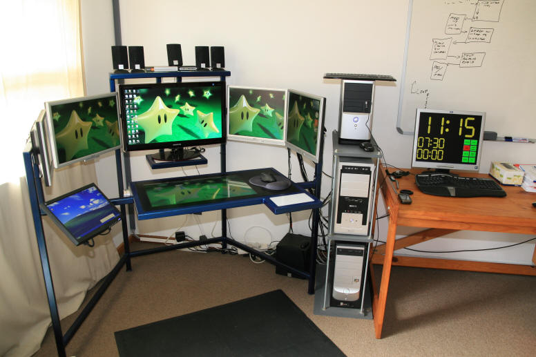
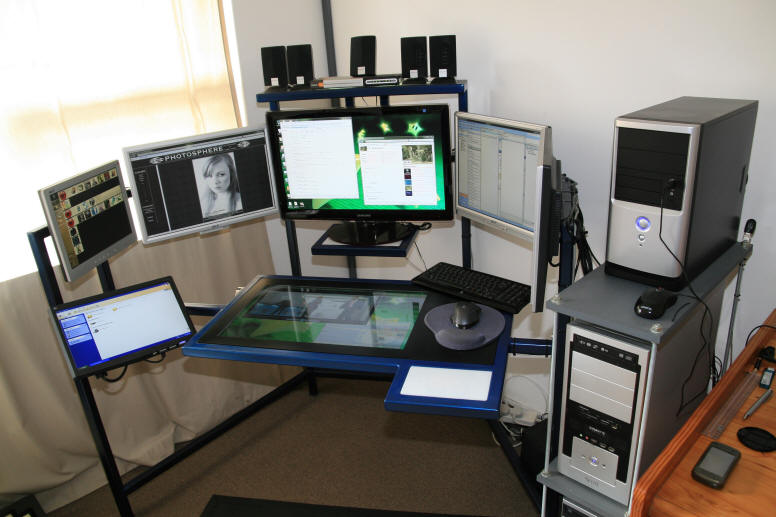
While searching for a new DIY project, I decided that it would be a nice idea to install an LCD monitor into the desk top of my computer desk.
Had I known how difficult the task would be, I may not have attempted it. But now that it is done I am very pleased with the results. I have again added something to my computer that you are not likely to find anywhere else.
The monitor that I used is the Samsung T260 26 inch monitor.
This used to be my primary monitor, but I replaced it for this project with the Samsung P2770 27 inch monitor which I first saw used on the computer desk of Gary Swartz.
Both monitors are brilliant articles of engineering and a credit to Samsung.
This project appeared to be relatively simple, but proved in the end to be one of the trickiest.
The problem is that these monitors are not designed to be disassembled and reassembled in another configuration.
Had my desk been a little deeper, I could have fitted the monitor in without disassembling it, but I wanted the whole thing to fit into my desktop which is only 30mm deep.
 |
 |
|
CONSTRUCTION | |
For those who may be interested in tackling a similar project, I have included further information below which will describe the problems that I encountered and how I overcame them.
If you are going to attempt this project, then I strongly recommend that you read on to avoid the headaches that I had with this endeavour.
If you do not have some level of experience in electronics, then I suggest that you acquire help from someone who does to see you through this project.
Unfortunately I did not photograph everything as I worked and some of the photos where taken with a cell phone and are therefore not top quality.
Nevertheless, here it goes.
The first thing to do is disassemble the monitor. This can be a little tricky and varies from monitor to monitor. Generally there are a couple of screws around the stand area. After that the sides usually clip apart, separating the front and back covers.
Unclip the monitor buttons and remove the innards from the outer casing.
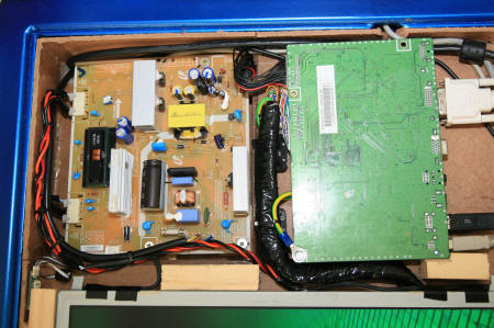
Next remove the metal cover from the monitor panel. Underneath you will find 2 circuit boards.
The one that the power cable plugs into is the Power Supply Board - also called the IP board.
The second is the control board which assists in creating the image on the monitor.
There will be a number of cables.
One from the PSU to the controller board. This feeds power to the controller. Then there is one from the controller to the panel itself. This carries the image data to the panel. Lastly there are 2 small cables from the PSU to the edge of the panel. These are the high voltage cables that power the backlighting of the panel. They carry over 1000 Volts, so take care.
Gently unclip all the cables and remove both circuit boards. Some monitors attach the boards to the removable cover. If this is the case, be careful when unplugging the cables. If your monitor is the type that has a flexi track cable between the controller and the panel, then you are on your own as to how to extend that cable. The T260 has a twisted pair cable of 30 cores.
In moving these boards to the side of the monitor, you will notice that the cables are too short to reach their sockets. This is where the problems start.
If you extend the Data cable ( between the controller and the panel ) then the image will become corrupted and distorted.
If you make the high voltage cables too long, it puts too much strain on the HT circuit and burns out your PSU. Yes I did that and had to replace my board. Finding a replacement board can be tricky. Pieter from VR Electronics in Port Elizabeth very kindly took the trouble to source the correct board for me, thus taking care of that problem.
Firstly overcoming the Data cable issue.
Lengthening the data cable opens it to interference and therefore corruption of the data.
This is how to make a cable that will work. Mine is 55 cm long and has no corruption at all.
Cut the data cable in half. Now there is no turning back.
Cut several lengths of CAT5 network cable. Take off the outer cover of the cable as well as the shielding, but do not unwind the cables. Solder each twisted pair of the CAT5 onto each twisted pair of the data cable - in so extending each twisted pair.
Now get equal length strips of RG 58 cable. This is a 5mm radio frequency cable and can be purchased from a computer, networking or radio shop. Make sure you buy a good brand like Kablecon. If the shielding is not tight, you will not be able to use it.
Now strip the metal shielding off the RG58.
Take this shielding and pull it over each of the CAT5 cables that you have soldered on.
Next solder the second end of the data cable onto your CAT5 extensions being very careful not to mix the cables up.
Pull the RG58 shields over your cable.
Solder a wire onto the circuit board end of the new cable and fit a lug to it. This will be used to secure the new cable to the earthling of the circuit board.
Lastly cover the entire cable including the CAT5 in RG58 with silver foil and cover that with insulation tape.
There is your interference free cable.
The second and simpler problem is the high voltage cable.
It does allow you to extend the cables to a point, but no too far.
If the PSU makes a whining sound, then your cables are too long.
THERE ARE DANGEROUS VOLTAGES ON THE PSU BOARD.
IF YOU DON'T KNOW WHAT YOU ARE DOING - DON'T TRY IT.
My problem was that the PSU had to be placed on the opposite side of the panel from where the cables emerge.
This meant that the cables had to be very long to span the distance.
To overcome this I had to shorten the cables by opening up the panel and turning the cathode ray tubes around.
Opening the panel is tricky.
They are not meant to be opened and can easily be damaged if disassembled.
If you are brave enough to try, then this is how its done.
Take all visible screws out of the panel.
Unclip the top and bottom covers.
Take the top cover off to expose the glass screen.
This screen has a delicate circuit attached to it by even more delicate flexi track cables. If you are not careful and damage these cables, you can throw your monitor in the trash.
Gently take the glass screen out and place it somewhere safe.
Underneath you will find a number of diffusers and Polaroid plates.
Make sure you know exactly how to put these back in exactly the same way that they came out.
Remove the large plastic light diffuser.
You will be left with 2 cathode ray tube lights at the top and the bottom of the housing.
Take them out and turn them around to place the cables on the opposite side.
Now reassemble everything exactly the way it came apart.
Small modifications may be required to get the cables out of the housing - BE GENTLE.
I also added a bigger heat sink to the High voltage switch on the Samsung PSU. More heat sinks will help dissipate the additional heat created by modifying the cable lengths.
These heat sinks have voltage on them, so don't touch them while the power cable is connected.
Also remember that this is a switch mode power supply which means that it can still retain voltage after the power cable is removed.
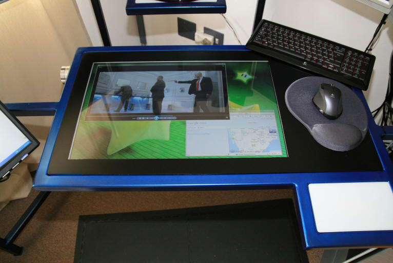
Another important thing to remember is that the monitor should be placed "upside down" in the desk top.
That is the top of the screen should be closest to the user.
That is because the monitor has a wider viewing angle when viewed from above than from below.
As for the construction:
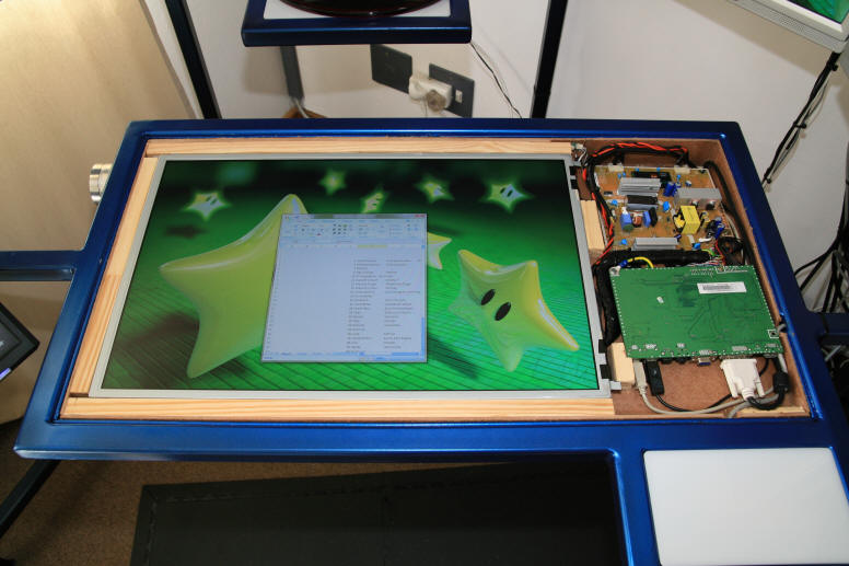
I encased the inside of my desk top with hard board from my DIY shop to insulate my metal desk from the electrical components.
I then added wood strips in the appropriate places to space and mount the components as in the pictures below.
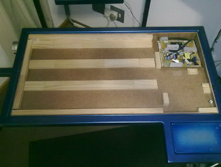 |
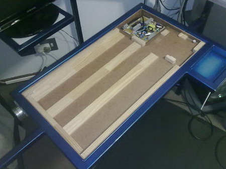 |
The panel and the 2 circuit boards are placed into the wooden framework and the cables are run. My controller board has a built in USB hub which I found useful for my cordless keyboard and mouse.
Make sure that your wiring cannot touch the heat sinks as they will heat up and melt through the insulation of the wires resulting in a bang with lots of smoke.
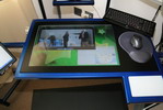
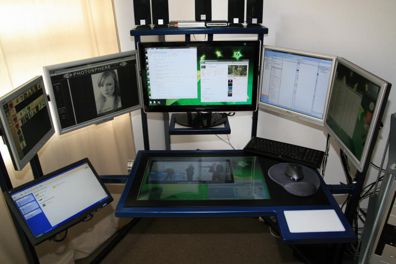
The following pictures show the placement of the components and the wiring.
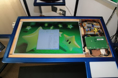 |
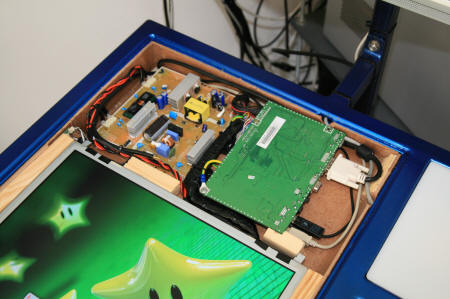 |
 |
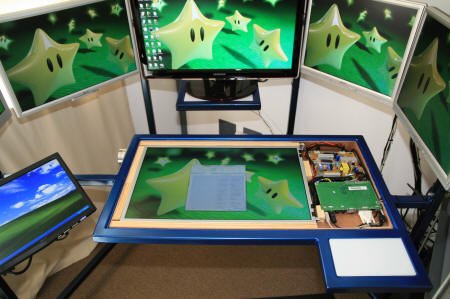 |
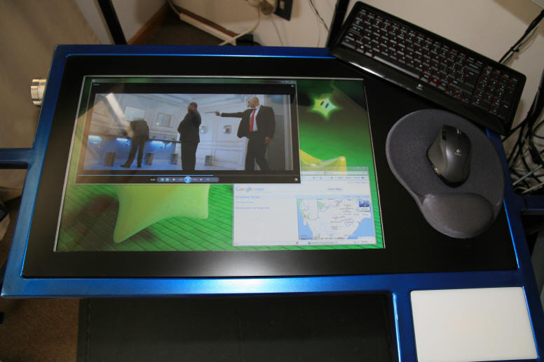
Lastly I covered the desk with 5mm transparent Perspex and spray painted the unwanted areas black.
This completes the construction of my Desptop Monitor.
After all the trouble I went through to make this work, I can say that I am very pleased with the result.
To anyone wanting to try this, I say go for it - the results are worth the effort. Just don't expect it to be easy.
 |
 |
 |
Good luck and thank you for visiting my website
I'm off to find my next project.