 |
QR CODE APP | |
 |
One day while sitting at the office I noticed a QR Code on the side of a product box.
For the first time ever I decided to take a closer look at it.
A myriad of
tiny dots in a precise matrix.
I became interested in understanding the format of the dots and how they constituted the message contained within the code.
That moment of curiosity launched me on a 3 month quest to understand and replicate the code by means of my own software.
This did not come easily though. The deceptively simple code has a brilliantly complex
structure behind it.
ORIGINS
The QR Code was developed in 1994 by Masahiro Hara who worked for a Toyota subsidiary company called "Denso Wave".
It is an acronym for QUICK RESPONSE CODE and was used in the company's manufacturing process.
Denso Wave still hold the patent to the QR Code but allow anyone to use it without license.
READING THE CODE
Reading the code is simple. Any smart phone can do it. Simply go to the Google Play Store or the Apple App Store and download a reader for free. I recommend "OK SCAN" as it has no adverts.
Creating a code is just as simple. A Google search will help you find one of many websites that have simple QR Encoders that are free to use.
I chose however to build my own encoder. This meant first understanding the code.
|
MY VB APPLICATION | |
Before looking at the structure of the QR Code, I would like to touch on my Application which I built in MS Visual Basic.
When I began the project I had no eventual use for the software.
I was simply interested in the maths and the code - and in understanding the structure of the elusive little matrix.
I might point out that the physical manual that I printed and bound containing all the information that I gathered in order to understand and build the QR Code program is over 4 cm thick.
The program itself weighed in at
13 982 lines of code - containing nightmarish maths.
Lets take a look at my Application for a moment:
 |
 |
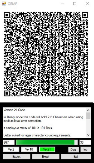 |
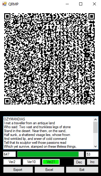
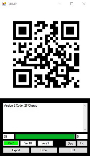
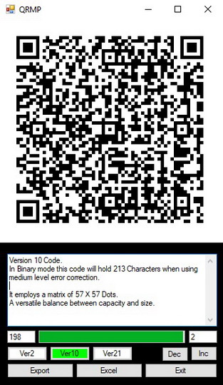
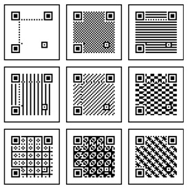
Above we see 3 captures of my QR Application.
Versions 2, 10 and 21 which are the only versions that I built into the program.
In total there are 40 versions, each a little larger than the one before.
Version 40, being the biggest, has a matrix of 177 X 177 and holds a maximum of 2331 characters when employing medium error correction (covered later).
When starting to type your text into my program, the code starts off as version 2.
As soon as it exceeds its capacity of 26 characters
it changes to version 10.
After exceeding that capacity of 213 characters it switches to version 21 which holds 711 characters.
Most web based QR encoders require that the user type the entire message before the code is generated.
I decided to generate the code with every new keystroke so that the user can see the code being created.
Just for interest sake.
The program also shows the user how many characters they have typed and how many are still available before the version increments.
Additionally it shows which version is in use and allows a different version to be selected - providing that it has sufficient space for the characters in use.
The export button creates a JPEG of the code and places it on the users desktop.
The size of the JPEG can also be varied with the INC and DEC buttons.
Lastly the Excel button.
That causes the program to
open a user defined MS Excel spreadsheet and import its information into a QR Code.
I then created a task specific version of this software to perform an automated task in conjunction with the Adroit SCADA software that I use at work. More on this later.
|
THE STRUCTURE OF THE CODE | |
Lets take a look at the structure behind the code.
Creating the QR Code can be broken up into 2 main parts.
The information string and the visual matrix.
The information string is a continuous string of ones and zeros which make up the formatting information, the message itself and the error correction code. Each black dot on the code represents a 1 from the string.
The matrix is the assembly of the information string into the image that the user scans.
Lets first look at the information string.
The first few digits of the string contain formatting information.
This tells the scanner about the nature and length of the message that it is about to read.
The first 4 bits (black or white dots on the code) are called the mode indicator.
This tells the scanner which of the four possible character modes are being used.
These are Numeric (Numbers only),
Alphanumeric (Numbers and letters),
Binary (All keyboard characters including special characters),
and Kanji (Japanese characters).
Each of these options allows for the use of more character options than the version before it,
but the sacrifice is that the higher the version (more characters available) the shorter the message has to be.
For example: In version 10:
The Numeric option allows the message to be 531 characters long.
If Alphanumeric is used then the same code will only hold 311 characters.
In Binary mode the character count is further reduced to 213.
For my application I selected Binary mode.
This meant a reduced character count, but I wanted the option of using special keyboard characters not catered for in Alphanumeric mode.
The next 8 to 16 bits contain the message length.
The scanner has to know how long the message is.
It then fills the unused space as the message length has to precisely match the maximum number of characters catered for by that version of the QR Code.
It also has to contain the length of the error correction section of the code.
The error correction section is a very interesting part of the code.
It is a mathematically generated string of digits built from the message that the user enters.
Its purpose is to automatically check for and correct any errors that the scanner may have made while scanning the code.
Not only this, but it can also recreate pieces of the code that are missing.
That is why you can still scan a damaged QR code where some of the image is torn off or covered.
This kind of error correction has been in use since the early days of computers and is mathematically fascinating in its composition and functionality.
The error correction section has four options:
These are labelled L, M, Q and H.
The higher the level of error correction selected, the more missing data can be recovered.
For example, option L will still scan if 7% of the code is missing, while option H will be able to scan if up to 30% of the code is missing.
The down side is that the higher the level of error correction selected the more digits it requires. This means fewer digits for the message itself.
High error correction level = shorter message length.
I selected the M setting for my application. It seemed like the best of both options.
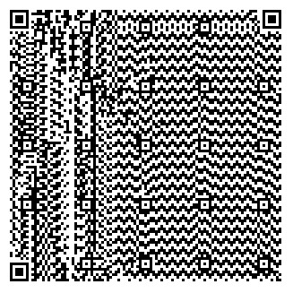
Here we see a QR Code that is made of a long string of the character "x".
With this we can see the separation of the message in the right 2 thirds and the error correction on the left third of the image:
 |
Lastly a Terminator is added to the end of the information string to ensure that the string contains the precise number of bits required by that version of the code.
The complete data string therefore looks like this:
Mode Indicator / Message Length / Message / Error Correction / Terminator.
It is assembled into an uninterrupted series of ones and zeros and passed on to the visual side of the compiler to be placed onto the image.
The length of the data string for a version 10 code is 1728 bits.
Version 40 requires a data string of 18672 bits.
And now the matrix, or the visual layout.
This is the visual component that the scanner sees, the little square made up of a matrix of tiny black dots.
As we have seen, the size and complexity of the matrix image depends on the version that has been selected.
The version is determined by how long the user makes the message.
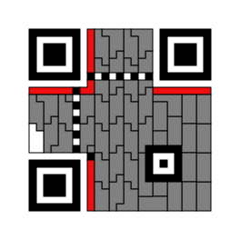
A small version, such as version 2, will have a matrix which looks like this:
 |
Whereas a version 21 code will have a matrix which looks like this:
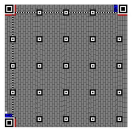 |
Each little grey block in these images is further broken up into 8 blocks of its own:
 |
The entire data string is then inserted into the matrix from beginning to end.
This is done from bottom to top and from right to left.
Each black dot represents a "1" from the string.
But I get ahead of myself.
Before the data string can be inserted, the rest of the image must me created.
Every single dot has a function and the code will not scan if there is an error in the basic layout.
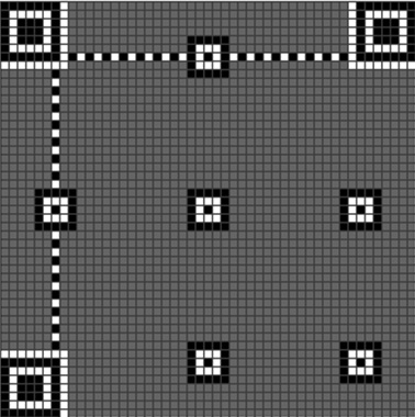 |
The large squares in the three corners are called the Finder Patterns.
Their function is to help the scanner align to the code for accurate reading.
The smaller squares scattered around the image are called Alignment Patterns.
They help the scanner align and read the code as well.
The bigger the code the more Alignment Patterns it will have.
The horizontal and vertical lines are called Timing Patterns.
They also assist with the scanning of the code.
The white spaces around the Finder Patterns are called the separators.
No code is entered into these spaces.
Format information is then placed around the separators:
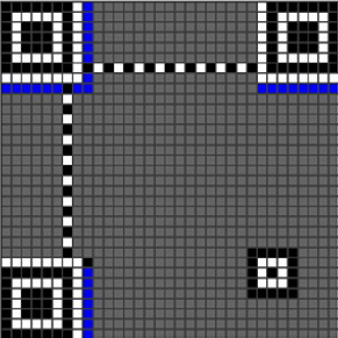 |
For Codes of Version 7 or higher an extra piece of information is added.
This new section contains version information and is placed as follows:
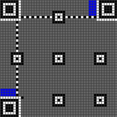 |
Almost complete.
Once the QR Code has been completely populated, a "Mask" is placed over it.
A mask can take 1 of 8 forms, as seen below:
 |
Its function is to make the code easier for the scanner to read.
Once the message is applied to the matrix there may be sections that are all black or all white.
This is difficult for the scanner to read.
When the mask is overlaid onto the matrix, any black dot reverses its colour if covered by anther black dot from the mask.
This removes large patches of black or white.
A series of calculations are conducted to determine which mask will be best suited.
In my app I simply selected mask 1 as a default. And it never fails to scan.
Once the Mask has been applied, the code is ready to read.
This is a very basic overview of the structure of the QR Code.
To actually produce the string and the image, a mass of calculations and configurations have to be executed.
The maths behind the error correction string is ludicrous.
Figuring
out the method and then writing the code to execute it took almost as long as the entire rest of the project.
|
REGARDING MY APPLICATION | |
For anyone planning to write their own software I would like to offer a suggestion.
At some point you will find yourself with 2 separate sections of code.
The data string and the visual matrix.
These will have to be combined in order to render your image.
What I did to simplify this process was to combine both sections into one master string containing every single dot that had to be placed.
It is a difficult job merging the 2 data strings, but it makes it far easier to render the image.
Once this was done I overlaid the mask onto the data string.
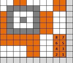
My layout plan for the version 2 code therefore looked like this:
 |
As you can see, I included the 4 block "Quiet Space" around the code into my data string as well.
This made the data string 1089 bits long.
When rendered, it produced every component of the image.
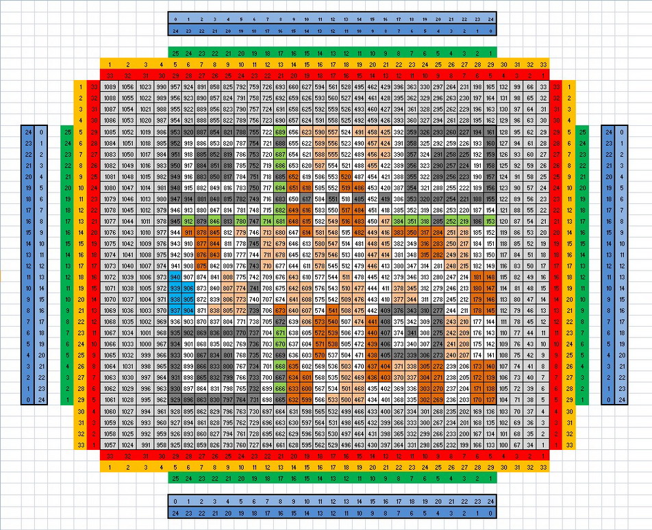
For interest sake, I include an image below of my Version 21 Layout plan.
It is too large to read the detail in this image, but it gives an idea of the complexity of the data string.
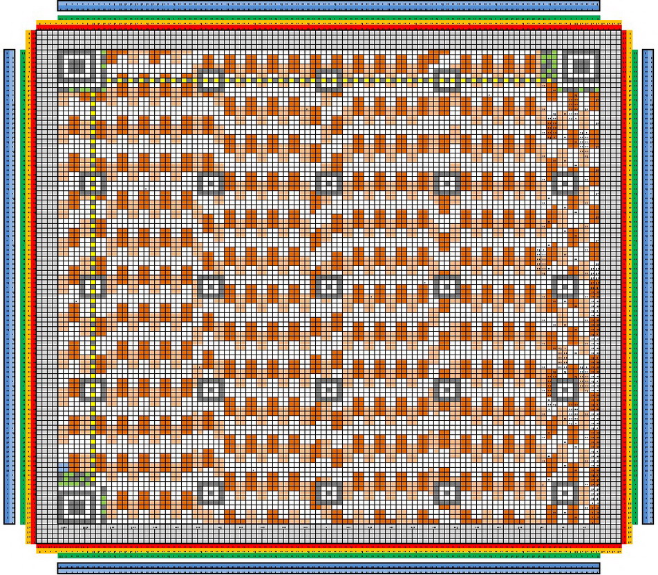 |
At this scale the numbering of the cells is not visible, but the combined data string is 11881 bits in length.
A colossal amount of work goes into the production of that data string.
But from it a complete and functional QR Code is produced.
|
AUTOMATING THE APP. | |
As I mentioned earlier, I wrote a task specific version of the application for use at work.
I wanted to incorporate it with the ADROIT SCADA Software that I use to monitor a bulk water reticulation system.
The idea is that a QR Code is automatically generated from the SCADA information every 5 minutes.
It is then placed onto the SCADA as an image which the operator can scan with his Smart Phone.
This scan contains current and relevant information regarding the reticulation system.
The operator or manager can then forward this information to his people in the field via SMS or WhatsApp.
Thus efficiently getting the information to the people who need it.
To make this work I wrote a script in the SCADA Software that dumps relevant information to an Excel Spreadsheet every 5 minutes.
The script then launches my application and shuts itself down.
My App reads the spreadsheet and renders the QR Code accordingly.
It creates a JPEG of the QR Code and shuts itself down.
The SCADA then collects the JPEG and displays it for the operator - as seen below:
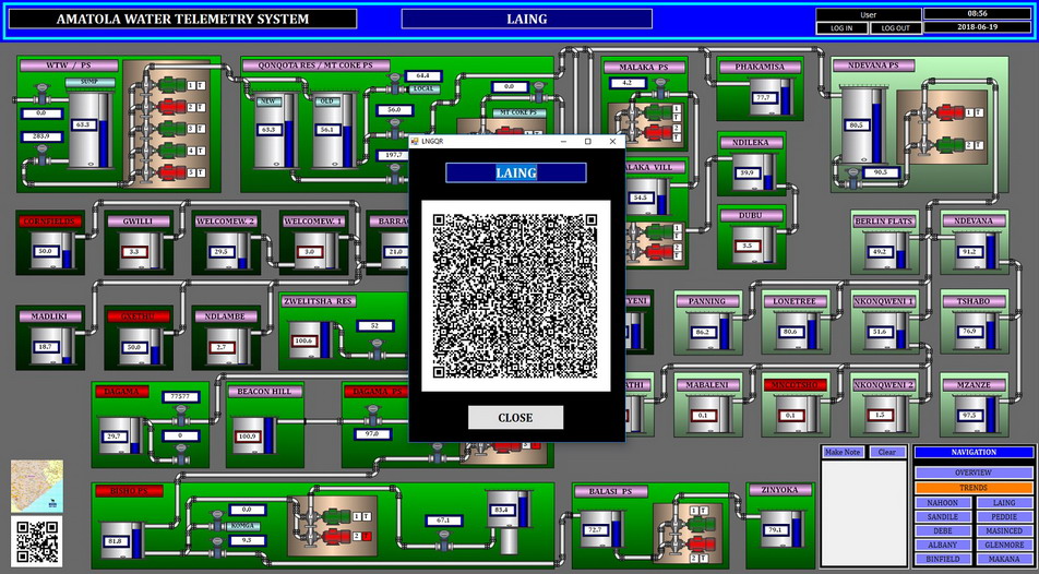 |
And that concludes my article on the QR Code.
Thank you for visiting my site. Please feel free to browse further.
And Lastly.
Hats off to
Masahiro Hara for developing this masterpiece.